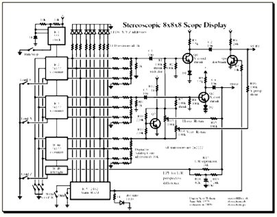
Schematic
pdf - ps - png
An electronic visual art project by Daren Scot Wilson
UPDATE 2024: This project could be good for a science fair project or used in some way for education. Kids these days, they know nothing about analog electronics! Imagine if the 4-bit X,Y,Z coordinates from the binary counters and the on/off bits stored in antique memory chips were generated by an Arduino wiht 8-bit X,Y,Z values. There are other possibilities. I can be available to help instructors and how-to writers with turning this old hobby experiment into a practical educational project suitable for modern times. See my contact info on my website's main page
This purpose of this project is to display a 3D grid of points as a stereoscopic pair on an oscilloscope screen. With a pair of cheap lenses one will be able to view the points in 3D in a manner like an old fashioned stereoscope but with modern electronics in place of photo prints. The device provides basic but believable perspective effects and allows a limited amount of rotation of the grid.
These 3D effects are produced entirely by analog electronics, using cheap and common parts likely to be in the possession of any moderately experienced electronics hobbyist.
A memory chip holds one bit for each grid point, so that it may be on or off, allowing for a crude form of drawing in three dimensions.
As shown, this device isn't of much practical use, but an enterprising student, 3D vision researcher, or mad scientist could find it an interesting start for an interesting project. Crazed art teachers handy with soldering irons might also find this fun. The right half of the schematic diagram that will be of interest; the left half as shown is just for initial experimenting. You will probably want to replace that left half with your own design.
Binary counters, 3 bits each, generate x,y,z values which are converted to analog by resistor networks. The outputs at the X and Y DACs show an eight-step staircase waveshape approximating a sawtooth wave. The Y staircase runs through one full cycle for each step of the X staircase. There is also a Z counter producing an even slower staircase wave, but we'll put that aside for now.
The x and y signals are sent to voltage-controlled amplifiers Q1 and Q2. The outputs of these are the main contribution to the main outputs to the scope. Transistor Q4 shorts out the Y output according to the contents of the RAM, which is driven by the X, Y and Z counters. Thus the bits in the memory control the presence or absence of each point of the 8x8x8 grid. If the rest of the ciruitry were removed, we'd be seeing an simple square 8x8 grid of green dots on the scope, with the ability to turn each one on or off with enough fumbling with the programming switches and buttons. Adding the Z circuitry will cause this 2D grid to be redrawn eight times, each time farther away. (or closer? I forget...)
The Z signal is used as the control voltage for the VCAs Q1 and Q2, applied by R1 and R7 from inverter Q3. The change in gains of Q1 and Q2 creates the appearance of shrinkage of the XY grid of points as Z increases. This is one important 3D effect - things getting smaller with distance. We are not trying for extreme closeup views or wild points of view; only a mild variation in gain is needed in this application. The potentiometers R13 and R14 mix a little bit of the Z signal, or its inverse provided by Q3, into the X and Y outputs. This causes the XY grids to slide in some direction as they shrink with increasing Z, producing a shearing effect. For small amounts, it fools the eye and looks like rotation.
The fourth bit of the Z counter is used as a left/right flip/flop. It flips state at the completion of each Z staircase cycle. The output is a square wave, added by resistor R17 to the horizontal output. This causes the separate left and right views of the grid to appear. So far, these two views would be identical. To create the stereoscopic 3D effect, these views must differ as if rotated (or sheared) a little. In the circuit, we need an effect like adding the Z or its inverse to the horizontal ouput, but we must have it differ between the left and right cases. The Z staircase signal will be repeating exactly the same in both cases.
We produce the desired perspective difference effect with a low-pass filter formed by R18, R19 and C5. When the L/R flip/flop goes high, the signal at other side of this LPF rises suddenly (due to R17) then slowly oozes up further as C5 charges. This oozing causes receeding XY planes in the right-hand view to shift rightward, which is the effect you'd expect when viewing the grid from a point of view displaced a bit to the right - as if from your right eye. The opposite occurs for the left-hand view. Together, this produces on the display a pair of grids as seen from either eye.
The original prototype was build on plug-in breadboard sockets using cheap commonly found parts any moderately experienced electronics experimenter is likely to have on hand. The 2102 RAM chip may be hard to find, since static RAM fell out of fashion long ago and now much larger amounts of memory are cheap and readily available. Feel free to substitute newer logic and RAM chips as you like.
Breadboard sockets are full of small stray capacitances. There are two places to be careful. The dot on/off switching transistor Q4 needs to switch cleanly; stray capacitance will lead to downward smearing of the displayed grid points. The other is where the L/R flip flop output feeds the horizontal output. Stray capacitance here will lead to a couple smeary streaks between the left and right versions of the grid. Even if stray capacitance can't be eliminated, the 3D effects should still be viewable.
While it may seem tempting to go for, say, a 1024x1024x1024 grid, this isn't a good idea due to the very wide range of frequencies involved from the very fast Y counter's least significant bits, to the L/R flip flop. It would be better to supply a series of X,Y,Z coordinates
Certain details of the digital portion are omitted, such as power, enable pins, etc. You are expected to know how to build circuitry with whatever logic family you choose - 74LS00, 4000-series CMOS or whatever. The 2102 RAM takes ten address lines, but only nine are used, so be sure to tie the tenth one to ground (or use it for crude two-frame animation).
Since the circuitry, as provided here, was only to demonstrate the concept and have a bit of fun, the design is not necessarily optimum. It merely works under good conditions. Various subcircuits are not well-isolated. For example the capacitor C4 at the collector of Q2 influences the workings of the waveshaping network of C5 and R17-19. Basic textbook circuit analysis probably won't work quite right.
The outputs X and Y expect a high impedance load, typical of all oscilloscopes since the 1970s. If you want to drive a display device with lower impedance, you'll want to add some sort of buffers.
The schematic was drawn using Postscript and Ruby. The file written to make this particular schematic, stereo888xy.rb, creates a Schematic class providing methods to draw diodes, resistors, lines etc between stated coordinates. Coordinates are kept in variables to allow arithmetic, making it easy to create equally space lines and adjust the positioning of parts in the schematic. Most of these coordinates are defined by the main vertical and horizontal lines determined from a hand-drawn schematic (from 1979, in this case) with further coordinates defined relative to these. See my Ruby and Postscript code on Github or use the links below (if they work)
Schematic and its methods are defined in a separate Ruby file which may be used for drawing other schematics. It takes canned Postscript code from dswschem.ps to define the details of drawing part symbols. This Postscript code was lifted straight out of my "Pure Sine Wave Generator" project, with a few minor tweaks.
The PDF file was made with the ps2pdf command line utility.
Recommended electron geek toy store: SparkFun
I thank my high school electronics instructor, Mr. Scharmen, for arranging a three hour block of time and the gift of independent study. Electronics class for everyone was at most two hours, but I showed such aptitude for designing and fixing electronic gadgets that the school granted me extra time. Without that I wouldn't have developed the hands-on practice, theory and intuition that let me do so many other things in the future.